Special Notice for European Union (EU) viewers. Due to the GDPR, you are NOT AUTHORIZED to access this website for any purpose whatsoever. Continued use is a violation of US LAW.
See the disclaimer for more information.
|

To understand how the remote control works, it is useful to review how a standard powered awning works. Review the graphic here. 12V and GND are fed into a double-pole/double-throw (DPDT) switch configured as a reversing switch (the switch has the crossover built-in). Then the motor is connected to each wiper contacts of the switch. The polarity is not critical, but will dictate which switch position is extend and which is retract. When we remote control the awning switch, we want to retain the mechanical portion of the switch so that in a boondocking situation, we can turn off the remote control to save on draining the battery, and just use the motor switch like it is here. While the standby current of a typical 433mhz remote relay is on the order of 5mA, which is not a lot - remember that there are other devices in the RV with similar standby currents, and all of those add up. Therefore it is best to consume zero current from these devices when boondocking. Boondocking of course means "dry camping"... running on batteries only without any 120VAC electrical service available. There are a few other design considerations which we will cover next.
My awning is a Dometic 9000 series, 13ft long. Dometic recommends a 15A circuit breaker for this circuit. However, analysis of the awning motor's current requirement reveals a maximum of just under 3A during the midpoint of the upswing (retract operation). This makes sense as that is in the area of maximum effort when retracting the awning. Deploying the awning takes much less current as the motor is assisted by gravity. One issue to consider is short-term stall current. This is the current demand when the awning reaches the end of travel and the operator is still depressing the switch to operate the motor. This stall current should be brief - assuming the operator has the common sense to release the switch at this point.
The limiting factor for the design is how much current the circuit board can handle - including stall current. For the traces and pads on the circuit board, a maximum of 0.12 inches width can be used. I can also specify a maximum of 2 Oz copper from OSHPark. The result is shown below (Calculated Trace Temperatures). The stall current appears to be around 8A, but we can still use 15A as a worst-case scenario as it would cover different awning lengths (longer awnings would have a higher current demand). As well, since the circuit will be fused at 15A (recommended by the Dometic awning installation manual), we need go no further. Also note that these calculations are for constant loads - not the brief period of time that will occur during a motor-stall condition.
Green = observed maximum operation current
From the table above, a therotical worst-case stall-current will heat the circuit board traces no more than 55 Deg F, which should be momentary. 55 Deg F is far below the melt-point of the copper traces, so the board should not become damaged. Still, it is prudent to protect the circuit with a fuse or circuit breaker.
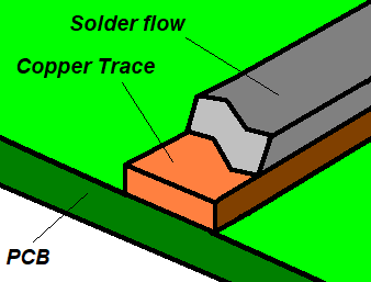
If more current capacity from the circuit board is requried, a technique called "solder tracing" can be used. Essentially it consists of re-flowing solder along the traces of the board, which adds more material, thereby increasing the current handling capacity. To accomplish this, I designed Rev B (Dtd: 8/6/2025) of the circuit board without a solder mask in the areas you may wish to reflow. This uncovers the bare copper traces so they can be solder traced. Tracing is simply done by applying a layer of solder over the copper trace with a solder iron. Normally this should be done with caution as it exposes current carrying conductors on the board which could be shorted if a metallic object fell on them. However, as we are potting the board, we are sealing the traces to outside contamination. Therefore, this is a safe and effective way to increase the current carrying capacity.
The most difficult part of solder tracing is to get a uniformly thick layer on the trace. For that reason, you should only expect a 40% or so improvement in current carrying capacity. While I did not see the need to solder trace the prototype in the video given the performance criteria of my awning motor, if you have a heavier duty motor, feel free to use this technique if desired. You may also wish to test the circuit board to ensure it can handle the current before installation.
The relays I selected for the awning circuit are Panasonic ACJ series as shown here. These are very powerful relays in a micro-package, and are rated at 20A for one hour, and an incredible 30A for 20 seconds (with only one of the two coils powered).
 Click on drawing for larger size
The primary difference between the ACJ2 and ACJ5 relays is the internal wiring. The ACJ2 is an 8 terminal relay, while the ACJ5 is a 10 terminal relay. For the ACJ2, the relay contacts are configured for motor reversing, while the ACJ5 must be externally wired for motor reversing if required. The tradeoff is that the ACJ2 requires less external wiring while the ACJ5 has a wider application. You can find the datasheet for the relays HERE.
 Click on drawing for larger size
My solution requires one ACJ2 and one ACJ5 relay as shown above. This is about as simple as I could make it, yet have the criteria of no-standby current, and a safety interrupt should both switches be depressed at the same time.
 Click on drawing for larger size
Also, a single ACJ relay could be used to accomplish the same task, however I do not like this so much as it requires the ground to be disconnected from the console switch. I just don't like having to modify things that way. As well, this might be a point of confusion for a subsequent owner of the RV or technician if for some reason the wireless remote must be removed. It's just not good practice in my view. If you want to use this solution, at least attach a terminal to the circuit board for the ground wire so that it at least appears to go somewhere.
 Click on drawing for larger size
There are of course other wiring schemes that would work but are not necessarily a good idea. For example, while the wiring scheme above will work, it can result in a direct short should the opposite function on both console switch and wireless relay be depressed at the same time. Trace the circuit assuming UP is depressed on the console switch while at the same time CH1 is active. Ground will be directly connected to 12V. Boom! While this may be an unlikely event, good engineering practices dictate that if something can happen, it eventually will happen. Always avoid the possibility of a catastrophic event occuring in your design. We could also use steering diodes, but 10A diodes are fairly large (we want to at least have an 8.5A current handling capacity), but that also means a larger circuit board - adding to the expense of the solution. Finally, a microcontroller could be used to perform the logic and ensure no shorts happen, but the microcontroller would have to be active all the time - which defeats our desire for a zero standby current solution in a boondocking situation.
While it is not absolutely necessary to build a relay board, it keeps everything neat and tidy. There are only a few components used on the board, so it is a simple board to build. The components you will need are as follows:
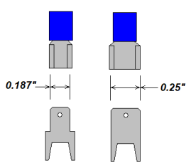
If you prefer 0.250 tabs, you should be able to substitute Keystone 1287 tabs for the 1285 tabs as specified above. That will allow you to use the more common 0.250 solderless lugs. The hole spacing is the same (0.200), but they are slightly thicker (0.052 vs 0.046) so you may have to push them into the circuit board with a bit of force. Populating the board is pretty simple with just a few components to install. It should be fairly self-explainatory so there is no need for a detailed parts placement drawing. Afterall, the relays will only fit one way. Optionally, you may wish to solder trace as explained above. When the board is potted into the box, about 1/16 to 1/8 inch of epoxy should be on top of the board. This will help secure the tabs, yet provide enough room to seat the connectors.

Once the board is constructed, wiring is pretty straightforward. You will want a source of 12VDC power that is switched so you can turn the relay receivers off in boondocking mode. For my RV, I dedicated an "Automation" switch for that purpose. It controls all of the receivers in the control panel so they can be turned off independantly. While the motor switch going to the relay board is polarity sensitive, you can simply reverse the polarity if needed. If the motor is opposite of the control - that is, if you depress the EXTEND function and the motor retracts, simply reverse the leads on the switch or relay board.
Note that the relay board receives power via a awning switch you will have to add. This is the Automation switch as shown in the drawing below. Any general purpose SPST switch will do (rocker, toggle, etc). This is necessary for the console switch to operate in boondocking mode. The relay board will not consume any power unless this switch is closed (and of course the wireless relays will not work when it is open).
 Click on drawing for larger size
Note that the quick connect tabs on the relay board are 0.187 wide. This requires a matching spade lug. While it is possible to use a more standard 0.25 lug, the fit will be sloppy. The 0.187 wide lugs are preferred (unless of course you swapped out the tabs for the 0.25 size ones).
0.187 width spade lug connectors.
Final preparation. While the wireless relays typically come pre-programmed, you will likely need to reprogram them. Typically the relays are programmed for LATCHING or TOGGLE mode; that is - when you depress the transmitter button, the relay closes and remains closed. Depress the transmitter button again, and the relay opens and remains open. This will not work for this project. The relays must be programmed for MOMENTARY operation. In this mode, the relay only stays closed while you are depressing the transmitter button. This is the preferred mode of operation. The programming is done in the relay receiver module - not the transmitter. Consult the owner's manual for the wireless relays for specific programming information.
Video
Advertisement
| ||||||||||||||||||||||||||||||||||||||||||||||||||||||||||